
Most commercially available and proposed CO2 capture systems use chemical solvents in a gas-liquid exchange column to separate the CO2 gas from a mixed gas stream. One challenge with these systems is that the absorption of CO2 into the solvent generates significant amounts of heat, thus increasing the temperature of the solvent as the gas passes through the column and creating a hot zone (temperature bulge). The capacity of the solvent to absorb CO2 suffers due to the temperature increase, which reduces the system’s efficiency.
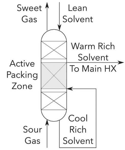
One solution to this challenge is introducing an intercooling device, typically a heat exchanger, to cool the gas. The solvent is withdrawn part way up the gas-liquid exchange column, cooled by the mechanical device, and then reinjected back into the absorption column; this describes the conventional ‘in-and-out’ intercooling method. The advantage of using this intercooling approach is it reduces to some extent the temperature bulge, thus also the required column height. However, LLNL researchers have developed a novel process design for intercooling using an ‘in-line’ method, a further improvement to efficiency over the traditional in-and-out approach.
The heart of this LLNL invention lies in combining existing concepts for absorber intercooling and packing geometry into a novel configuration that yields the benefits of in-line intercooling at reduced capital cost and equipment size. The technology utilizes LLNL-developed Triply Periodic Minimal Surface (TPMS) structures (US Patent No. 11,389,765) that are produced using additive manufacturing (AM) techniques. In the novel process design, the flowthrough in the gas-liquid exchange column remains continuous without the need for any solvent withdrawal and reintroduction as required by an in-and-out approach.
Innovatively, within a portion of the column, while the solvent and gas phases flow through one domain, a secondary cooling fluid flows through an internal, separate set of channels. The structure of the heat exchange packing allows for a large surface contact area between these two domains, which in turn should allow for very efficient removal of heat that can then be used elsewhere. Employing TPMS structural geometries improves the energy efficiency of the process while minimizing the height of the column, even more so than the traditional intercooling methods and with a smaller capital equipment outlay.
Related Publication: Moore, T, Nguyen, D, Iyer, J, Roy, P, Stolaroff, JK. Advanced absorber heat integration via heat exchange packings. AIChE J. 2021
Left Image Source: stock.adobe.com
Right Image Caption: process flow diagram where in the ‘Active Packing Zone’, the rich solvent flows through cooling fluid domain of the 3D printed active packings, absorbing heat from the solvent and gas phases, which flow in separate domains.
- In situ absorber intercooling eliminates the need for expensive, separate external cooling devices.
- Reduction of the “temperature bulge” or hot zone, is expected to reduce the required absorber height by about 10-20%. Modelling results suggest that compared to a conventional CO2 capture system, the LLNL design can reduce the column height by 10 - 20%.
- Waste heat released by exothermic reactions within the absorber is recovered, reducing the reboiler heat duty and energy requirements of the process.
Large scale carbon capture process for industrial applications (e.g., coal gasification or coal-fired power generation, ethanol production, fertilizer production, natural gas processing, refinery hydrogen production).