The Laboratory has several decades of experience in the development of EMBs. In the course of this development several prototypes that advanced the technology were constructed and their designs were licensed. Work is now underway at the Laboratory to develop new types of EMBs with the objective of bulk storage of electricity at utility scale. This new generation of modular flywheel storage systems is based on the use of some special technologies, including passive magnetic bearings and a novel type of electrostatic generator that is very light in weight and, since it has near-100 percent efficiency, does not require active cooling. In these respects these new designs differ greatly from present commercially available flywheel storage systems. As noted above, the purpose of this FBO is to make U. S. Industry aware of an opportunity to participate in the development of EMBs specifically designed for vehicular use.
With minor exceptions, at present all electric vehicles are powered by electrochemical batteries, with their well-known limited deep-discharge cycle life and modest electrical turnaround efficiency (70 to 80 percent). Electrochemical batteries in principle could continue to fill the storage demands of electric vehicles, but they fall short in three areas. The first is their limited cycle life under deep discharge conditions. Despite many decades of development the best of such batteries typically have a deep-discharge cycle life of about 1000 cycles, requiring operation under restricted depths of discharge to achieve multi-year lifetimes. Second, the "turnaround" energy efficiency of electrochemical batteries, being typically of order 80 percent, lowers the overall energy efficiency of the vehicle. It also limits the efficiency of regenerative braking, a technique that is important in increasing the range of the vehicle per kWh in its battery pack. Third, the electrochemical batteries in present use carries with them problems of overheating and catching on fire, and also involve the disposal of hazardous waste, problems that are not an issue with the EMB.
The New Technologies:
The integration of 3 key technologies distinguishes LLNL's electromechanical battery (EMB) from present-day flywheel systems. These technologies are:
Electrostatic Generator/Motor (ESG):
(very high efficiency with near-zero internal heat generation, utilizing an extremely simple and lightweight structure, eliminating point-loading stress-induced areas).
Passive Magnet Bearings:
(special permanent magnet arrays are used to levitate and to dynamically stabilize the rotating flywheel system, eliminating the need for complicated sensors and control circuits, which in turn, eliminates heat generation in the vacuum chamber and the corresponding active cooling system required).
Carbon Fiber Composite Flywheel rotor employing special mechanical designs:
(high-strength, low-density carbon composite material enables increased kinetic energy storage while achieving significant system weight savings).
Additional attributes of LLNL's EMB include:
- Projected 95% storage efficiency.
- Simple and straightforward architecture promotes low cost, and high reliability.
- Long "standby" energy storage lifetimes due to extremely low parasitic losses.
- Long device lifetime as a consequence of 100% passive magnetic bearing design (no electromagnets), resulting in no frictional wearing of components and no heat-related issues.
- No loss of capacity from number of charge-discharge cycles.
- Near-zero internal heat losses from the electrostatic generator/motor and the passive magnetic bearing system, thus no requirement for an active cooling system.
Modularity, The Battery Pack, and Predicted Range:
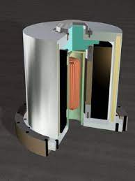
As is the case with electrochemical batteries when they are used in electric vehicles, an EMB battery pack would be made up of many individual "cells". That is, the pack would be made up of several EMBs whose rotors would likely be about the size of a large coffee can. To minimize external gyroscopic effects the battery pack would be made up of pairs of counter-rotating flywheels. The pack would then contain as many such pairs as required to achieve the desired range of the vehicle. Preliminary computer-based studies of example designs indicate that for a comparable weight and size of battery pack, the EMB-based one should be capable of doubling the range of the vehicle as compared to today's electric vehicles based on present-day electrochemical batteries.
The design calculations that have been performed in exploring the potentialities of LLNL's new approaches to flywheel energy storage have been built on existing and past LLNL flywheel programs, including a program aimed at flywheel systems for the bulk storage of electricity at utility scale. To achieve the requirements of such systems, as mentioned above, LLNL has developed some key new technologies, technologies that we believe are unique to flywheel energy storage. These developments came about because the LLNL researchers came to the conclusion that with vehicular applications, as with the present program on bulk storage, the proposed new-generation flywheels must break with past tradition in critical technological areas. The first of these is the generator/motor. In all commercially available flywheel storage systems built to date, this component consists of an electromagnetic-type generator. This generator must operate within the evacuated housing of the flywheel rotor, using internally mounted high-field permanent magnets and internally located windings. In addition to the mechanical issue of the high centrifugal force load caused by the magnets, even when no power is drawn from the system there exist parasitic losses associated with eddy currents induced in the windings and in other metallic parts. When power is drawn, the ohmic power losses in the windings lower the system efficiency and represent a substantial heat source that requires an active cooling system. The LLNL-proposed answer to the first of the three technological areas is to replace the electromagnetic generator with an electrostatic (E-S) one, building on the pioneering work of John Trump at M.I.T. in the 1950's. In this type of generator/motor the heavy magnets located on the inner surface of the flywheel rotor are replaced by lightweight electrodes (the generator/motor "rotor"). These electrodes face another set of electrodes (the "stator") that, together with the rotor electrodes, form a time-varying capacitor. The system is charged through special charging circuits that employ parametric resonance effects that can increase the power output by more than an order of magnitude over that obtainable using the Trump design. In this type of generator the internal efficiency of the generator is essentially 100 percent (the only significant losses are in the external power electronic components that permit generator (discharge) and/or motor (charge) functions. When not generating or motoring, the parasitic losses of this system are zero. Also, preliminary experimental model tests together with computer simulations have shown that the generator output of this new E-S generator/motor should be more than adequate for vehicular applications, actually substantially exceeding the power output of present electric vehicle battery packs.
The fact that the peak power output of the electrostatic generators of an EMB battery pack for an electric vehicle can substantially exceed the peak power requirement of the vehicle means that the electrostatic generators of the battery pack can deliver the power required for the vehicle through their parametric resonance circuits to the output electrical bus at a very high efficiency. In an example case where the EMB battery pack power output was assumed to be operated at 50 percent of its absolute peak value the calculated generator efficiency at the output bus of each module of the pack was 98.5 percent, far higher than that possible from an electrochemical battery pack.
The second key technological innovation is the bearing system. Because mechanical bearings operating in a vacuum have limited lifetimes and significant parasitic losses, present-day commercial flywheel storage systems have adopted the use of magnetic bearings to support the spinning rotor. However, all magnetic levitation systems, including maglev trains, must deal with the constraints imposed by Earnshaw's theorem. This theorem, posited in the early 1800's, shows that it is impossible to stably levitate any array of permanent magnets by the magnetic forces exerted by another, stationary, array of permanent magnets. A loophole for the magnetic bearing problem is that Earnshaw's Theorem only applies to static systems. Stable levitation is possible if dynamic effects can be employed. The commercial flywheel systems therefore employ what is known as "active" magnetic bearings. In an active bearing system, electromagnets driven by power circuits that are controlled by sensors that detect unstable motion and, in turn, control the magnet power. Such bearing systems are expensive, require maintenance, and represent an internal parasitic power loss (in the electromagnets) that requires active cooling, and can lead to appreciable energy losses during standby times of the flywheel system.
Given the above-listed negative features of active magnetic bearing systems the LLNL approach is to replace the stabilizing elements of the active magnetic bearing by a purely "passive" stabilizer. That is to say the entire magnetic bearing system is composed simply of annular arrays of permanent magnets that provide contactless levitation. Their Earnshaw-based instability is overcome by a passive system that uses flywheel rotation to generate a stabilizing force. An example of such a stabilizer is one that consists of a set of magnets on the inner surface of the rotor (typically using "Halbach arrays" of permanent-magnet bars). These rotating arrays interact with a stationary set of windings to produce a restoring force that overcomes the inherent instability of the levitating permanent magnets. In a typical form of the stabilizer the windings are located at a "null" point in the Halbach array magnetic fields so that current is only induced in the stabilizer windings upon motion away from the force equilibrium plane of the levitating magnets. In operation, therefore, the losses of the stabilizer approach zero, except in those cases when there exist accelerations of external origin.
Since in vehicular applications the EMBs will experience g-level accelerations in normal driving, momentary-contact "touchdown" bearing concepts have been conceived and these would be investigated in the course of the development.
Predicted Self-Discharge Times:
For electric vehicular use an important parameter of the energy storage system is its self-discharge time. For the new LLNL EMB we believe that this time can be many weeks in duration, for the following reasons: First, standby losses of the E-S generator are zero. Second, when the vehicle is parked the losses of the passive bearing system can be reduced to near zero. Contrast this with flywheel systems with integrated permanent-magnet-based generator/motors and active magnetic bearings. Here there are eddy-current-based losses and active-bearing power demands that substantially shorten the self-discharge times.
The remaining source of losses is aerodynamic friction. At the operating vacuums, of order 10-5 Torr, calculated self-discharge times from aerodynamic friction are several months. That such vacuum pressures can be maintained in a sealed-off vacuum vessel containing a carbon-fiber/epoxy rotor was demonstrated in a flywheel-related experiment performed at LLNL in the 1990s. In this experiment, after the vacuum vessel was pumped down long enough to outgas the rotor, it was sealed off and its pressure was monitored. It was found that the pressure stabilized at 2.0 x 10⁻⁵ Torr, remaining constant for a period of two months, at which time the experiment was accidently terminated.
Energy and Power Density Parameters:
Using computer simulation codes that were benchmarked either by independent code calculations or by laboratory test models, the critical parameters of energy density (watt-hours/kg) and power density (kw/kg) were calculated for modular EMBs that were of a size that would be appropriate to package together to form battery packs with dimensions comparable to those of present-day electric automobiles, such as the Tesla Model S or the Nissan Leaf. One example calculation employed EMBs each of which occupied a cubical volume measuring 30 cm. on a side, i.e. a volume of 0.027 cubic meters. The volume of the Leaf battery pack is approximately 0.5 cubic meters so that one could fit 18 of the example EMBs into a battery pack of the same volume.
Assuming a rotor employing high-strength T1000 carbon fiber and epoxy composite, each EMB in the example case would store about 2.5 kWh of energy (90 percent of the full-charge energy, assuming discharge to 30 percent of initial rpm) so that the total stored energy would be about 45 kWh, more than twice that of the present Leaf battery pack. Also, the calculated peak power output at full charge of the special-design electrostatic generator of a single EMB was 50 kW. Thus in principle the present 90 kW requirement could be met by only two of the EMB battery pack modules. In practice this would allow the operation of the battery pack EMBs at power levels well below their full-charge peak power.
Comparing the calculated Watt-hours per kilogram of the example EMB battery pack with that of the Leaf battery pack, the latter is 68 Wh/kg, while the estimated EMB battery pack value using T1000 carbon fiber composite is 200 Wh/kg. (Using the lower-cost IMS65 carbon fiber the code-predicted energy density is 140 Wh/kg.)
Module Size Considerations:
In the discussion above an example was given of a LEAF-size battery pack made of 18 EMBs each of which would occupy a cubical volume measuring 30 cm. on a side. An optimized design, however, might use EMBs of smaller dimensions, owing to the scaling laws of important performance parameters that apply. For example, since the power output of the E-S generator scales as the square of the rotor radius, while the energy stored varies as the cube of the radius, smaller radii are favored if high power density (Watts/m3) is desired. Also, and especially relevant for vehicular applications, is the fact that the ratio of angular momentum of the rotor to stored energy decreases with rotor radius, again favoring smaller rotors. Thus the optimum size of the EMB rotors might be substantially smaller than the one picked for the example, as determined finally by unit cost and system complexity issues.
Special Issues for Vehicular Use of EMBs:
To complete the description of the computational and design results to date, they have also included conceptual designs of all of the major components of an automotive EMB module, including "touchdown bearings" to handle the expected accelerations that would occur in operating the vehicle, together with conceptual designs of the vacuum vessel that would also act to contain the fragments resulting from failure of the rotor together with the fragments of other elements, such as the magnetic bearings and the electrostatic generator. As was shown in a picture that was obtained of a failed commercial flywheel with a carbon-fiber composite rotor, upon failure the rotor turned into "cotton candy" that was completely contained by the vacuum chamber. Only if there are heavy and structurally strong rotor components, such as large rare earth magnets for the generator/motor, does containment become a serious issue. Because of the use of an electrostatic generator motor with its lightweight rotor electrodes, together with passive bearings made up of small magnet elements, the new-generation LLNL EMBs should have a minimal containment problem.


Current Status of Development and Go Forward Plan:
The development and testing of LLNL's EMB system is a "work in progress" at this time. The present effort is directed toward the bulk storage of electricity for utility and other applications. Both an E-S generator/motor system and a passive magnetic bearing system have been designed and fabricated but are in various stages of assembly and have not been through our test validation program. The design of these systems is based on the predictions of several computer codes that were written to evaluate the theoretical design model and system performance. To further substantiate our design philosophy, an independent code evaluation was done by a professor and his graduate student at Carnegie-Mellon University. Their code results confirmed those obtained at LLNL.
Consequently a key result from this phase of work is to show that the measured performance/empirical data obtained so far agree closely with the code predictions. Benchmarking the computer codes developed to predict system performance is a key milestone in demonstrating the EMB's viability as an energy storage system.
The work to-date directed toward EMBs for vehicular applications has been limited to computer simulations using the above-described codes and to preliminary designs. These calculations have been very encouraging, but clearly need to be confirmed experimentally using real hardware. Continuation of this work would therefore involve the design and testing of prototypes en route to a complete unit. At that point the development and testing would be ready to be taken over by Industry, en route to commercial production.
A notional schedule of our Go-Forward plan is shown in the Project Plan below, depicting the major activities. We are very conscious of the desire to have a working prototype as soon as possible, and the proposed work plan supports that understanding. The first 9 months of the program will be to engineer, design and build a working prototype, typical in size to what would actually be used in a vehicle. The following 3 months would be dedicated to testing this unit in our High Pressure Laboratory at LLNL, which has been prepared and approved to support this test program. Testing will include understanding the flywheels energy storage capabilities, system efficiency, etc. and comparing the real data with our computer simulation codes and predictions. A preliminary budgetary cost of $10M for the Year 1 effort is proposed. If additional funding became available, the first six months of Year 2 could be used for in-vehicle testing, gathering real on-the-road test data, and ensuring that the engineering challenges of vehicle shock, vibration, maneuvering (cornering, braking and accelerating) and gyro-dynamics have been successfully addressed. The in-vehicle tests could be accomplished, for example, by replacing the 1.2 kWh battery pack of a Prius hybrid auto by one or two of the prototype EMBs developed in the Year 1 program. In an earlier, similar, in-vehicle testing program at LLNL, a Prius was converted to operate on hydrogen and then was equipped with a composite-based high-pressure hydrogen fuel tank that had been developed at the Lab. It was then driven around the Laboratory for a distance of 650 miles without refueling.
Patents
Some of the key EMB patents by components are the following (this is not an exhaustive list):
1. Composite Flywheel Rotors:
- U.S. Patent No. 5,924,335 Concentric Ring Flywheel with Hooked Ring Carbon Fiber Separator/Torque Coupler, by Thomas C. Kuklo, issued 7/20/99 (LLNL Case No. IL-9373)
- U.S. Patent No. 5,941,132 Concentric Ring Flywheel without Expansion Separators, by Thomas C. Kuklo, issued 8/24/99 (LLNL Case No. IL-9374)
- U.S. Patent No. 5,775,176 Separators for Flywheel Rotors, by Thomas C. Kuklo, issued 7/7/98 (LLNL Case No. IL-9490)
- U.S. Patent No. 5,778,735 Interlayer Toughening of Fiber Composite Flywheel Rotors, by Scott E. Groves et. al., issued 7/14/98 (LLNL Case No. IL-9584)
- U.S. Patent No. 6,756,091 Lightweight Flywheel Containment, by James R. Smith, issued 6/29/04 (LLNL Case No. IL-10160B)
2. Electrostatic Generator:
- U.S. Patent No. 7,834,513 An Improved Electrostatic Generator/Motor, by Richard F. Post, issued 11/16/10 (LLNL Case No. IL-11575)
- U.S. Patent No. 8,264,121 Improved Electrostatic Generator/Motor Configuration, by Richard F. Post, issued 9/11/12 (LLNL Case No. IL-12230A)
- U.S. Patent No. 8,643,249, Improved Electrostatic Generator/Motor Configurations, by Richard F. Post(LLNL Case No. IL-12230B)
3. Passive Magnetic Bearing System:
- U.S. Patent No.5,495,221 Dynamically Stable Magnetic Suspension/Bearing System, by Richard F. Post, issued 2/27/96 (LLNL Case No. IL-8764)
- U.S. Patent No. 5,847,480 Passive Magnetic Bearing Element with Minimal Power Losses, by Richard F. Post, issued 12/8/98 (LLNL Case No. IL-9784)
- U.S. Patent No.6,191,515 A Combined Passive Magnetic Bearing Element and Vibration Damper, by Richard F. Post, issued 2/20/01 (LLNL Case No. IL-10420)
- U.S. Patent No. 8,760,021 A Centrifugally Decoupling Touchdown Bearing, by Richard F. Post, filed 5/31/11 (LLNL Case No. 10421)
- U.S. Patent Application Publication No. 2011/0291508 Combined Radial Stabilizer and Centering Element for Passive Magnetic Bearing Systems, by Richard F. Post, filed 6/1/11
Two recent technical papers are provided for review:
- Post, Richard; Summary of Projected Power and Energy Density Parameters for the "New Generation" LLNL Electromechanical Batteries, June 24, 2013; LLNL-TR-640475
- Post, Richard; Computer Simulation of an Electrostatic Generator: Example Case; April 26, 2013; LLNL-TR-635770
Companies interested in commercializing LLNL's Electromechanical Battery energy storage system are asked to contact Genaro Mempin. Please describe in the email your company's development plan, outlining:
- Planned number of Prototypes
- Development schedule for each Prototype
- Date of expected First Commercial Sale
- Resources available (or plans to acquire the resources necessary) to execute the planned schedules to achieve First Commercial Sale